Pressure Swing Absorber inspection
Industrial context
A Pressure Swing Adsorber (PSA) systems are widely used for applications such as hydrogen purification and the production of oxygen or nitrogen from air, serving industries ranging from chemical processing to medical oxygen generation.
The PSA are ferromagnetic assets, mainly A516 Gr 70 with a thickness that can vary between 10mm to 60mm. The adsorbers’ dimensions can vary depending on the design and production, with the majority being around 30mm-40mm for the thickness. The PSA’s size can also vary, with adsorbers © 2023 The Authors. 0being as large as 1m to 3m in diameter and 5m to 15m in height.
The number of welds will also depend on the design and dimensions, typically it is usual to find 3 to 5 circular butt welds, so 2 to 4 longitudinal butt welds along with a top and bottom nozzle.
Fatigue cracking, driven by cyclic or fluctuating stresses over long periods, is a frequent damage mechanism in PSA vessels because of the inherently cyclic operation of swing adsorption.
Routine inspections are essential for ensuring the safety, reliability, and long-term performance of assets. Given the hazardous nature of hydrogen production and separation, PSA vessels require thorough and regular examination to provide continuous monitoring and risk mitigation.
Traditional manual inspection methods often require extensive scaffolding just to access the asset, adding significant time, cost, and safety risks to the project. Manual ultrasonic testing (UT) further limits efficiency by capturing only a single reading at each point along a grid. While generic PAUT techniques can be applied to inspect PSA vessels, they often lack a dedicated interface tailored to the vessel’s geometry and operating conditions. This limitation can reduce inspection efficiency and make it more difficult to capture the full range of relevant damage mechanisms with accuracy and consistency. Without automated defect detection and sizing the inspection process relies heavily on manual interpretation. This not only increases the risk of missed or underestimated indications, but also slows down analysis and reporting.
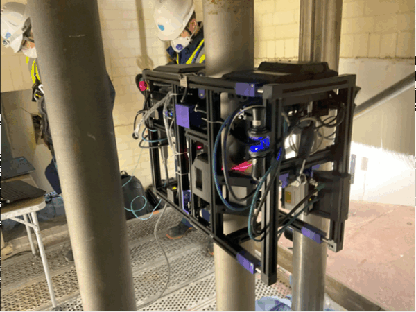
A comprehensive inspection solution has been developed by Ekoscan for PSA (Pressure Swing Adsorption) vessels. The system features the IBEX automated scanner, equipped with two PAUT probes utilizing TFM (Total Focusing Method) technology to ensure high-resolution imaging. To optimize inspection efficiency, Plane Wave Imaging (PWI) has been integrated with a laser-guided scanning system, enabling faster data acquisition without compromising quality. The weld path is tracked with precision through laser guidance, while a machine vision camera detects and avoids obstacles in real time. A dedicated software interface has been designed to allow inspection parameters to be configured according to the specific geometry and requirements of each vessel. Automated defect detection and sizing capabilities have been implemented to reduce operator dependency, improve consistency, and deliver reliable results. Through these innovations, PSA vessel integrity assessments are performed faster, safer, and with greater accuracy than conventional methods.
By integrating automated scanning, PWI acquisition, TFM imaging, and auto-analysis, the PSA solution delivers substantial gains across the entire inspection workflow.
Time Savings – PWI drastically reduces acquisition time. Automated defect detection and sizing remove subjectivity, ensuring repeatable, code-compliant results regardless of operator skill level. This shortens inspection cycles and keeps fabrication or maintenance projects on schedule.
Cost Efficiency – Faster inspections and fewer manual operations translate directly into lower labor costs, reduced downtime, and improved asset availability.
Higher Asset Reliability – More thorough and accurate weld assessments mean earlier detection of critical flaws, preventing costly repairs or unplanned outages.
Sources
- Total Focusing Method: Theory and applications
Roy, O., Holmes, C., Fink, M., Journal of Applied Physics, vol. 114, no. 5, pp. 054901, 2013,
DOI: 10.1063/1.4811197 - Plane Wave Imaging for ultrasonic NDT: Optimization of inspection parameters for welds
Neau, G., Reverdy, F., NDT & E International, vol. 98, pp. 12–22, 2018,
DOI: 10.1016/j.ndteint.2018.04.003 - Adaptive Plane Wave Imaging for complex geometries in ultrasonic testing
Voillaume, H., Raillon, R., Caleiro, C., IEEE Transactions on Ultrasonics, Ferroelectrics, and Frequency Control, vol. 67, no. 3, pp. 587–598, 2020,
DOI: 10.1109/TUFFC.2020.2971234 - Comparison of TFM and PWI for defect characterization in austenitic welds
Raillon, R., Voillaume, H., Research in Nondestructive Evaluation, vol. 30, no. 4, pp. 237–256, 2019,
DOI: 10.1080/09349847.2019.1631854 - Ultrafast ultrasonic imaging for NDT: Application to weld inspection with matrix arrays
Roué, D., Goursaud, S., AIP Conference Proceedings, vol. 1839, no. 1, pp. 020008, 2017,
DOI: 10.1063/1.4981210 - Plane Wave Imaging with limited-angle data: Application to weld inspection
Chassignole, B., Billebeau, B., Ultrasonics, vol. 113, pp. 106502, 2021,
DOI: 10.1016/j.ultras.2021.106502 - Advanced ultrasonic imaging techniques for NDT: From FMC to PWI and TFM
Benoist, P. (CEA LIST), IOP Conference Series: Materials Science and Engineering, vol. 188, no. 1, pp. 012012, 2016,
DOI: 10.1088/1757-899X/188/1/012012